Micro:bit motor hardwired without motor board
The output pins on the micro:bit can only supply a small amount of current, not enough current for a power demanding device such as a motor. A transistor can be used to solve this difficulty.
A transistor is like a fence gate for electricity, a small amount of current can be used to open the fence gate to allow a lot of current to flow through to power demanding components.
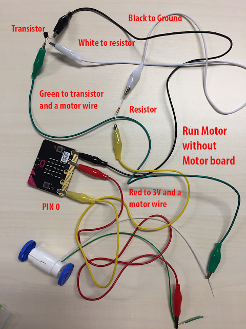
This is an example of building a micro:bit motor circuit with crocodile leads to join the components together.
When connecting the transistor it is important to correctly identify the Base, Collector and Emitter leads. See image. Care needs to be taken when connecting the transistor to make sure there are no shorts. It is recommended you bend the pins away from each other before you connect the crocodile leads.
Microsoft has changed their URL for creating code. Go to:
https://makecode.microbit.org/ and enter the following lines of code. Modify to your requirements.
A transistor is like a fence gate for electricity, a small amount of current can be used to open the fence gate to allow a lot of current to flow through to power demanding components.

This is an example of building a micro:bit motor circuit with crocodile leads to join the components together.
 |
| Transistor |
 |
| Resistor: red, red,red, gold |
Microsoft has changed their URL for creating code. Go to:
https://makecode.microbit.org/ and enter the following lines of code. Modify to your requirements.
 |
| Coding for a motor |
How it works:
We want the power to pulse on and of and the width of the pulses are controlled to drive a motor. This process is known as Pulse Width Modulation (PWM). By changing the percentage of the time that the transistor spends on (known as the duty cycle) the speed of the motor can be controlled.
This code works in two stages. The first loop writes the duty value to Pin P0 then increases the duty value by one and writes the value to P0 again. This repeats until the value reaches the maximum of 1023 (full speed).
The second loop then kicks in and reduces the duty by 1 and writes it to P0 until the value reaches 0 (stopped). This whole cycle is inside a forever loop so the motor will speed up and slow down forever.
The PWM output varies the duty cycle of the output voltage, as show below, to vary the speed of the fan motor.
More information can be found at: https://www.kitronik.co.uk/blog/experiment-4-using-a-transistor-to-drive-a-motor/

Comments
Post a Comment